|
|
|
|
Identifying Engines & Parts |
|
Abbreviations:
DEW
=
Detroit
Engine
Works.
WMC =
Wadsworth
Manufacturing
Co. DMCSC =
Detroit
Motor
Car
Supply
Co.
CEC =
Columbia
Engine
Co.
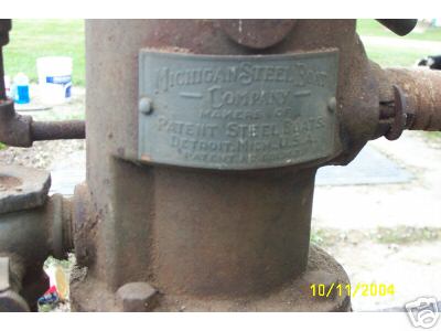
MSBC =
Michigan Steel
Boat
Co.
DBC =
Detroit
Boat
Co. SMPC =
Standard
|
|
The information on this page was collected from original
Detroit Engine Works, Detroit Motor Car Supply Co. & related
companies manuals, parts bulletins, patents, ad literature,
etc... That has been scanned and posted on this website and is believed to be
accurate. If you have original
literature, documentations, photos that you
would like to donate so that other collectors and restores may view this
information. please e-mail me.
mazak@rocketmail.com ____________________________________________________________________________________________ There are a number of companies
that manufactured engines stationary and marine that appear to look just
like or very similar to the DEW two cycle style engines produced back in
the early 1900's. The information below will explain what some of the
differences are on the engines manufactured or
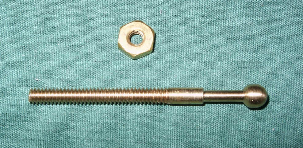
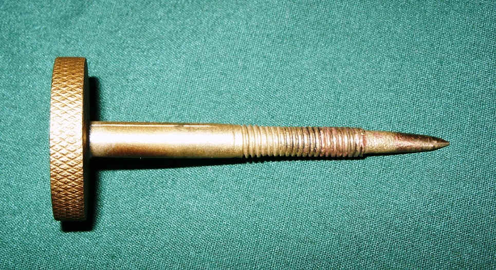
sold by DEW, DMCSC, CEC, MSBC, DBC, CPMC, MEC, BGEC, PIW. CPMC
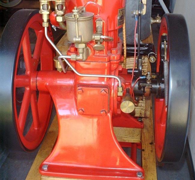
stationary engines also have unique features such as the tapered
ends of the crank shaft with nuts used to hold the flywheels on . Most
of the DEW style stationary engines used gib keys to secure the
flywheels. Air
intake & governor arm on the CPMC engines are cast different then DEW styles. (See photos
CPMC section). These unique features make this companies engine easy to
distinguish from other DEW style engines.
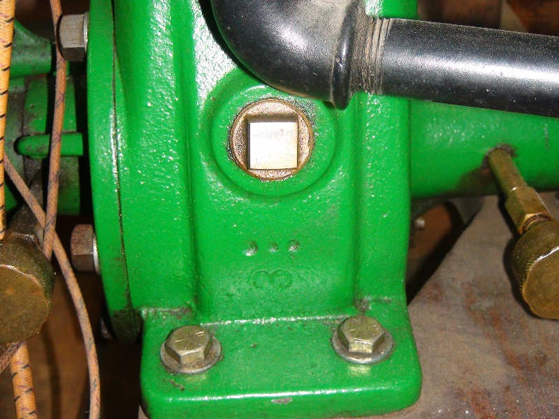
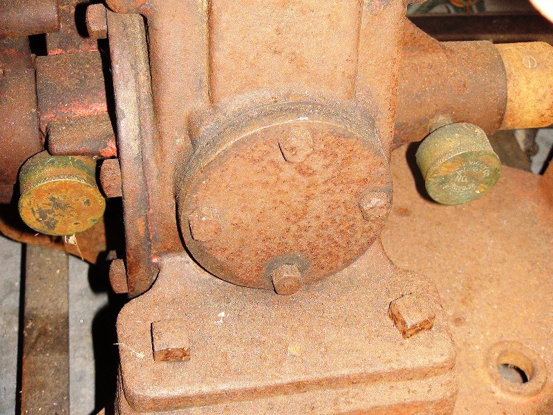
1st early style
Inspection hole 1900 - 1907
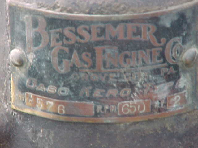
Also if you have a Detroit type stationary engine with
two flywheels that has no name tag it will be difficult to figure out who
the manufacture is unless it is a Middleditch or Bessemer these engines
are fairly easy to identify from a DEW or DMCSC by looking at the fuel
injector, exhaust manifold, engine base, cylinder shape, etc..
____________________________________________________________________________________________ |
|
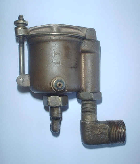
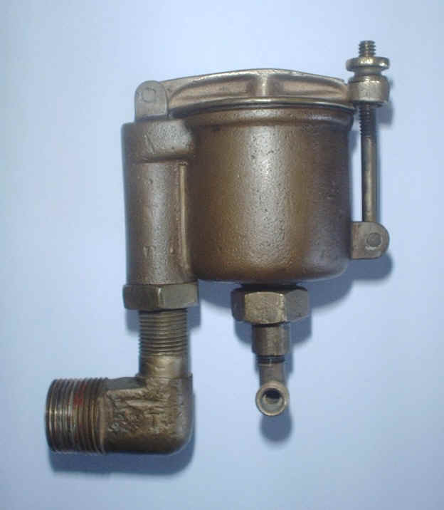
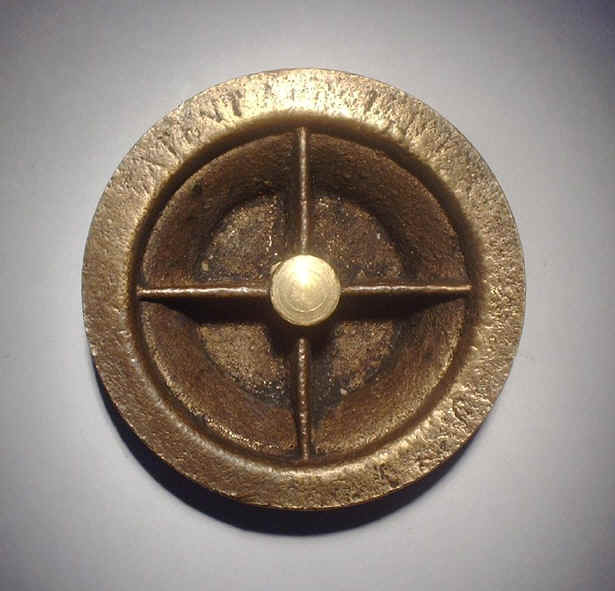
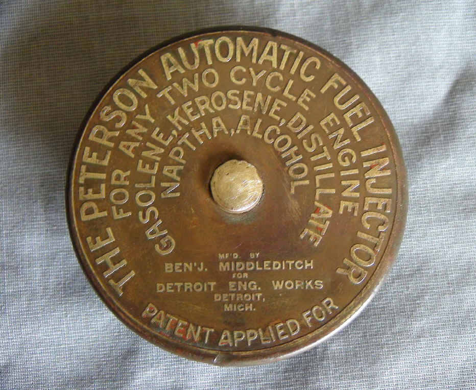
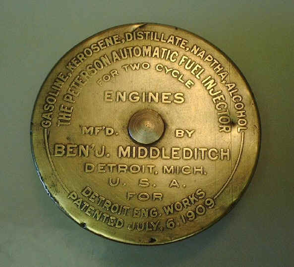
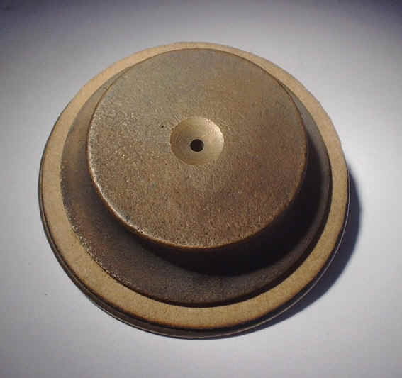
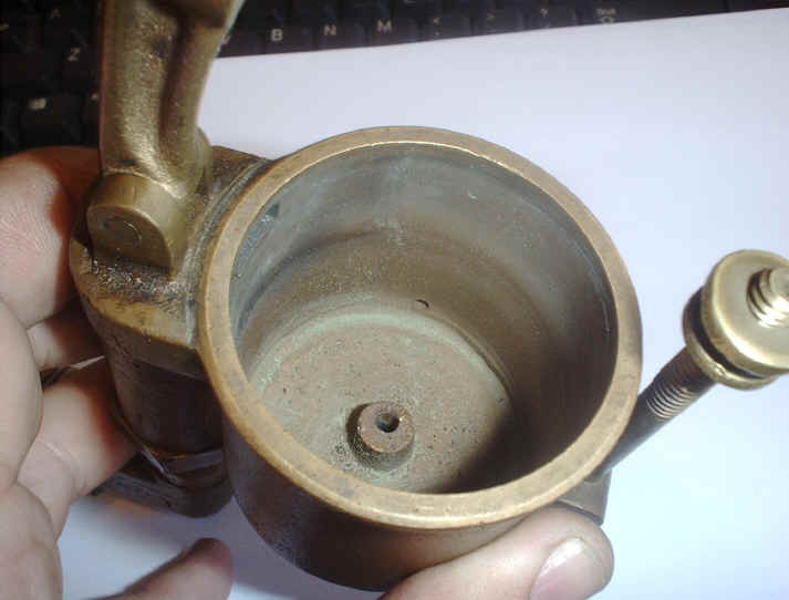
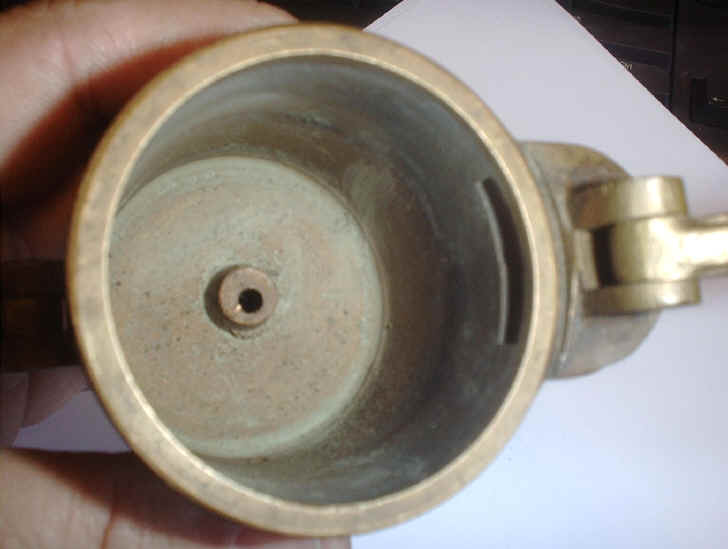
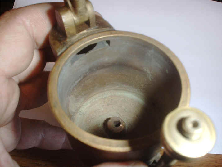
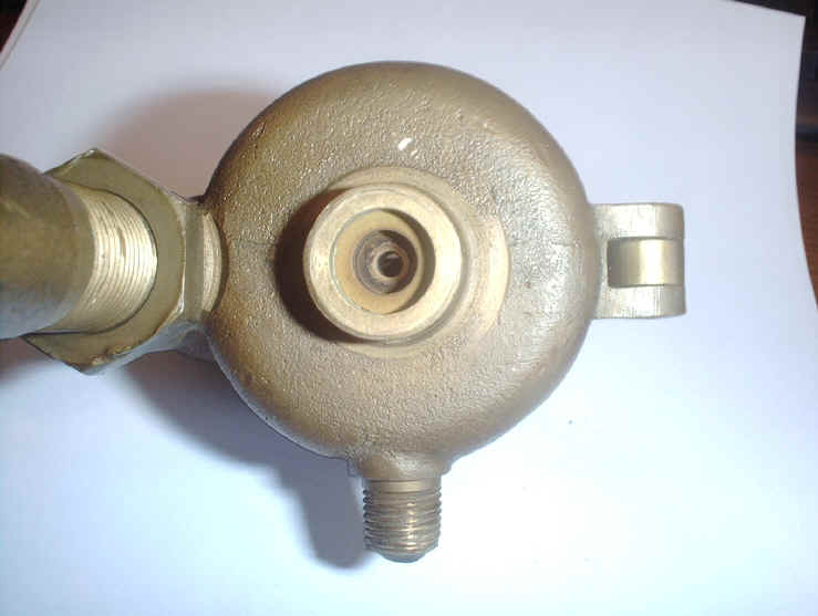
Peterson Automatic Fuel
Feeder-Injector |
|
The early two piece Automatic fuel feeder-injector (patent # 926,892) was designed by John Peterson and Frederick O. Peterson patented on July 6, 1909 manufactured by Ben J. MiddleDitch for DEW. Application for this patent was filed on Feb 24, 1908 and it appears that this fuel injector was produced a number of years before being patented in 1909. A DEW engine catalog dated 1907,1908 shows this same fuel feeder-injector with a ribbed fuel reservoir cap, see photo's below. Original literature shows that this early style fuel reservoir-injector was used on DEW, DMCSC stationary and Marine engines. At this time I do not have proof that this fuel feeder was used on other brand name engines but there is a good possibility that is was. Sources = (1906-1908 DEW Catalog), (U.S. Patent # 926,892), (1909 DEW Catalog), (Part List Bulletin No. III Jan 1st 1912), (Parts List Bulletin No. III part 3 Nov 1st 1914), (1915 DEW Catalog), (Information embossed on Peterson fuel feeders).
(patent #
926,892)
|
|
Barthel Automatic Fuel Feeder-
Injector
|
|
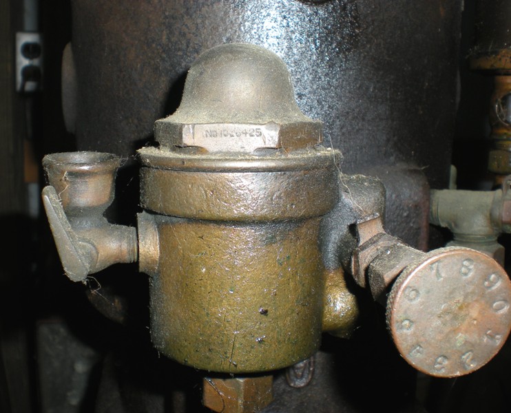
The one piece fuel feeder-Injector (patent # 1,026,425) was designed by Frederick Barthel
assignor to Frederick Wadsworth who owned & managed Detroit Engine
Works. The patent application for this fuel feeder was filed on Jan 7,
1911 but they were being manufactured by DEW sometime before 1911 and then patented May 14, 1912. There were 3
different versions of this one piece fuel feeder/Injector produced. All three
versions were patented under the same patent number. They are
listed below in the order in which they were produced.
Sources=
(U.S,Patent
# 1,026,425), (Part List Bulletin
No. III Jan 1st 1912), (1913 DMCSC Catalog), (Parts List Bulletin No. III part 3 Nov 1st 1914), (Parts List Bulletin No. III
Jan, 1st 1915), (1915 DEW Catalog).
Literature shows the first style being used on DEW, DMCSC stationary
engines. I'm sure that all three fuel feeder versions were
probably used on other make and/or style engines.
_____________________________________________________________________________________________________________
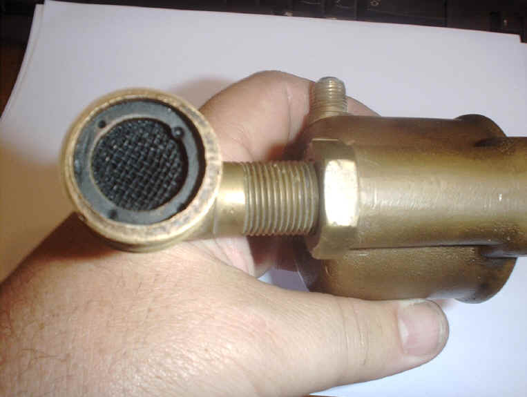
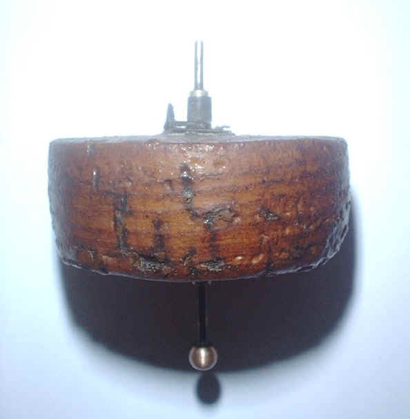
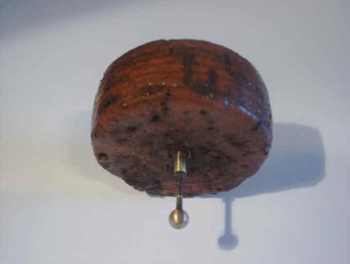
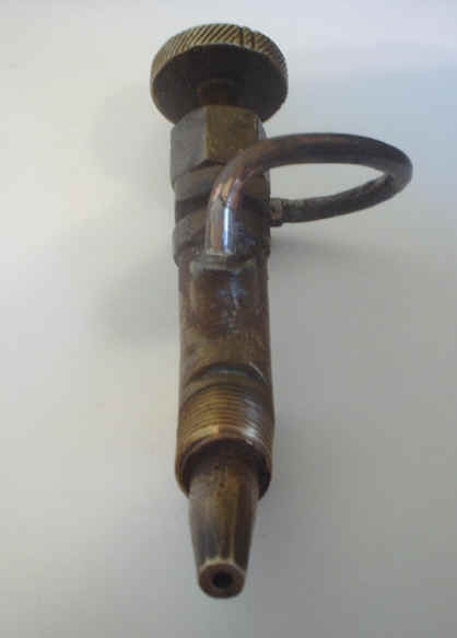
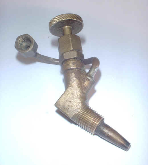
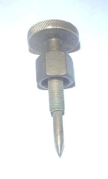
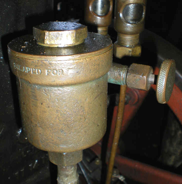
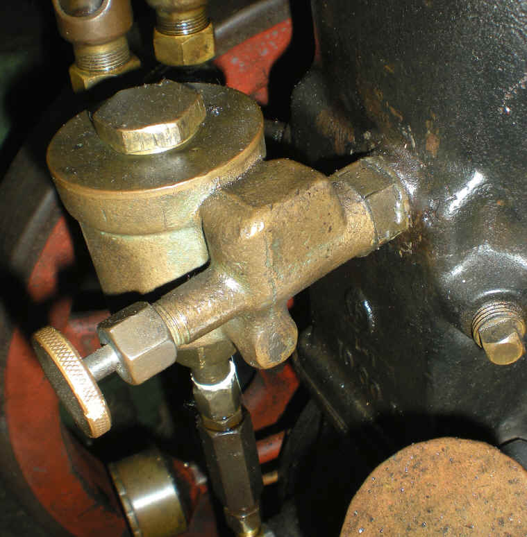
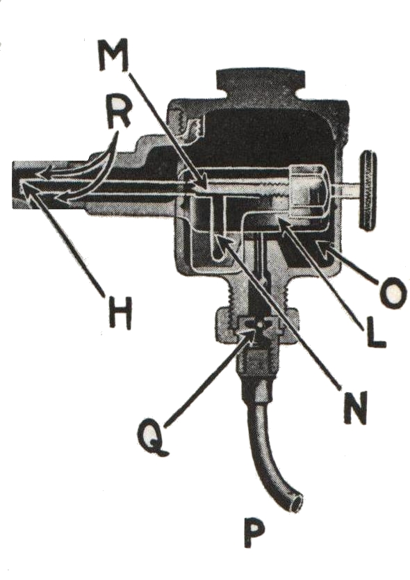
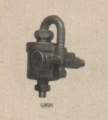
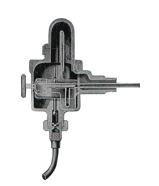
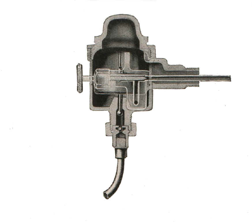
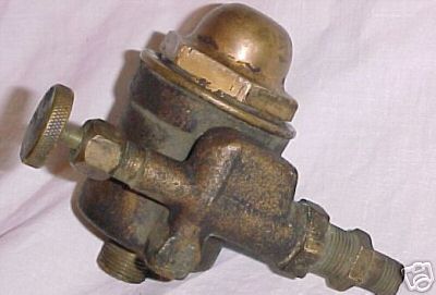
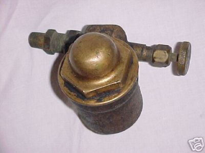
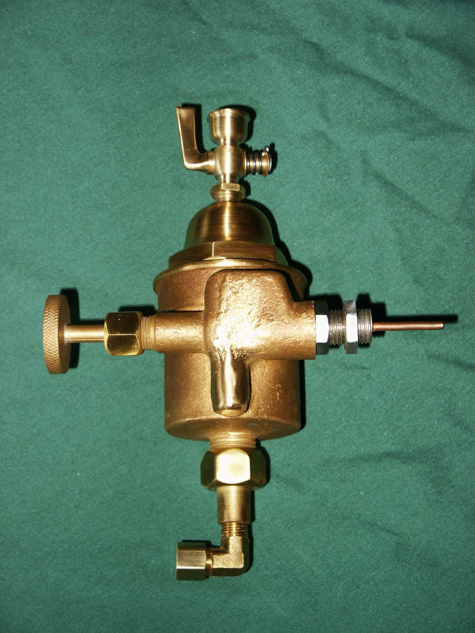
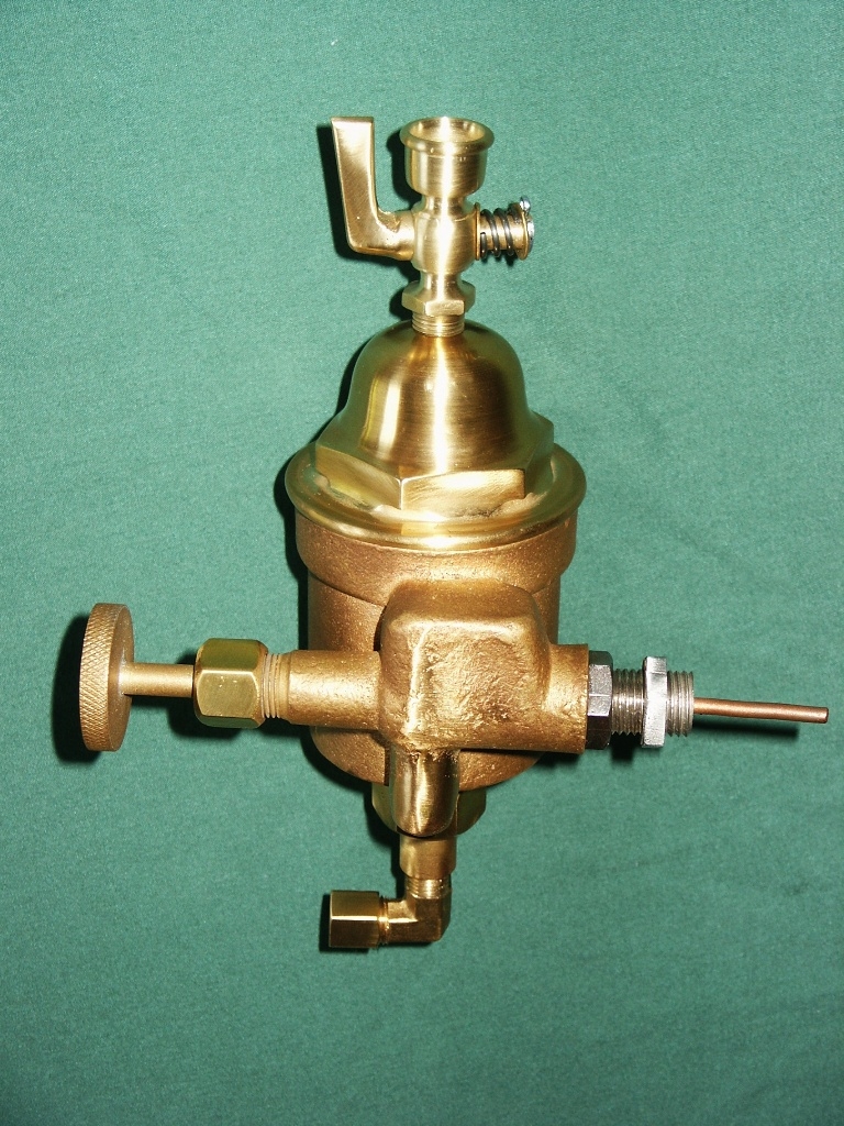
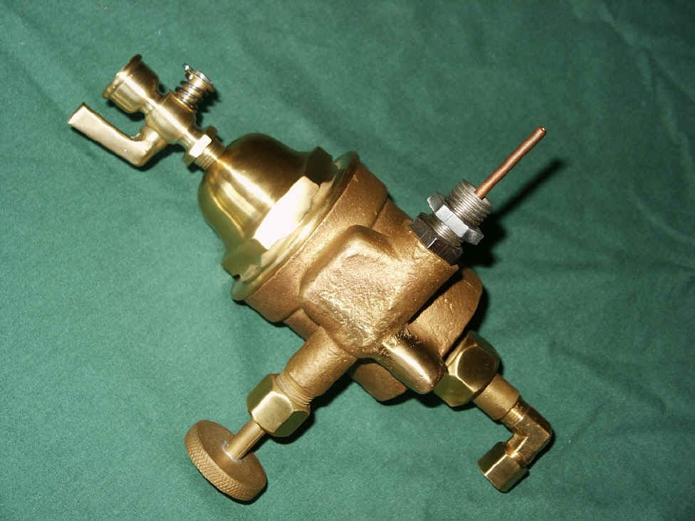
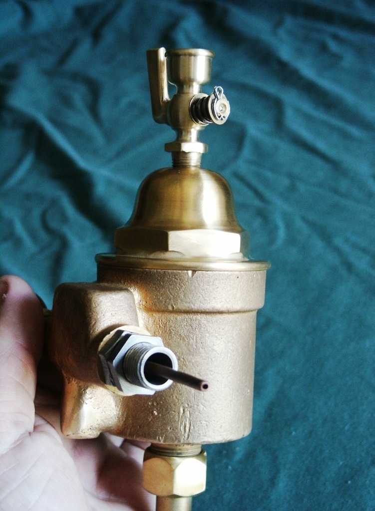
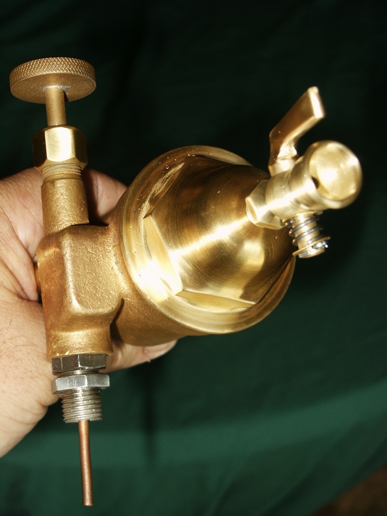
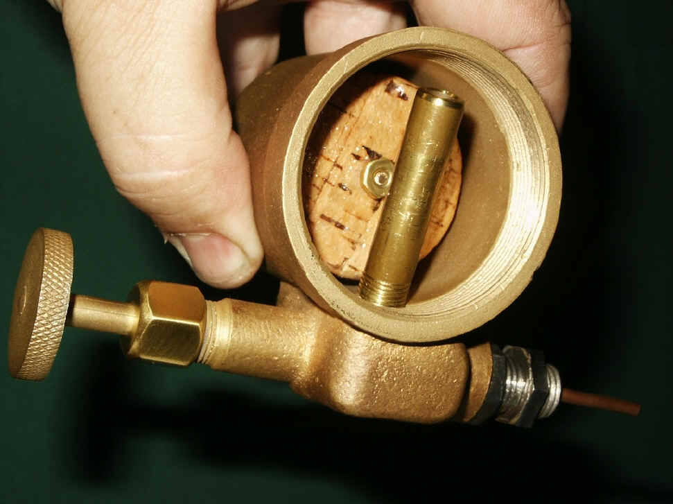
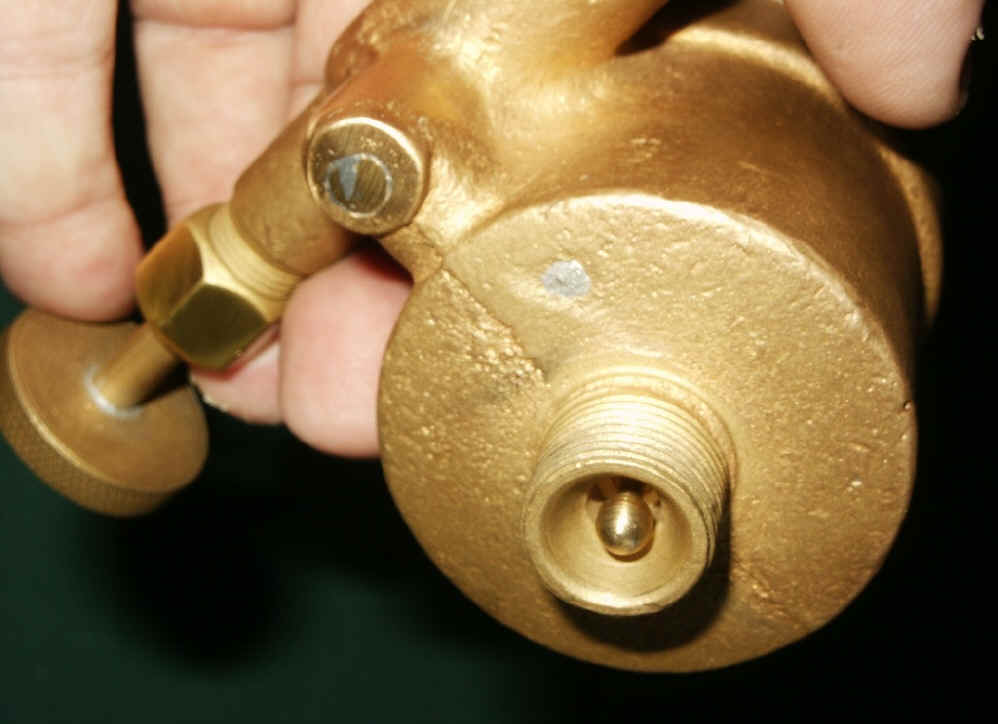
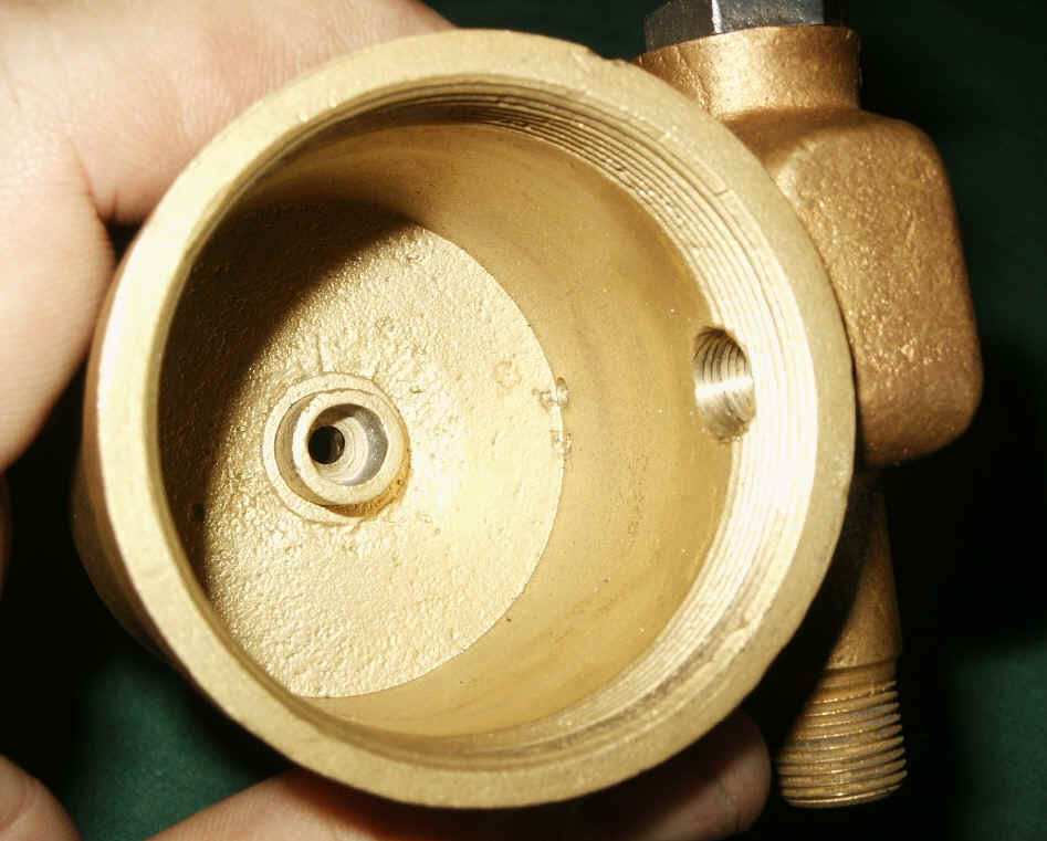
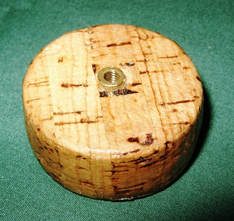
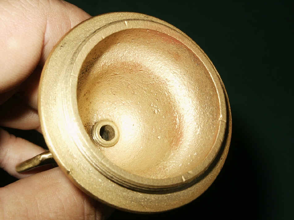
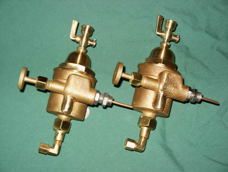
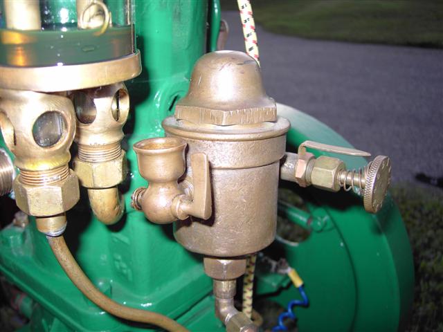
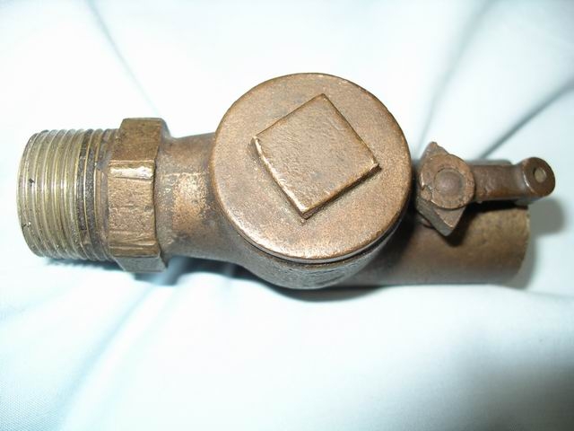
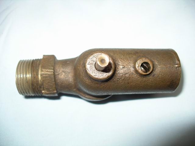
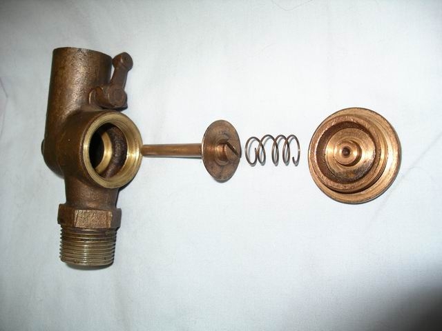
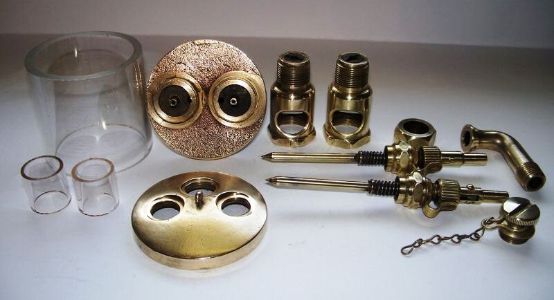
3rd version 1911-12
This 3rd version fuel feeder had a new improved top cap which was
rounded and set higher allowing for the 1/4" pressure/vaccum tube inside
the reservoir to set higher above the fuel level. The new cap is
referred to by many collectors as the acorn top fuel feeder. This
modification was also introduced
around the 1911-1912 time period and was the last fuel feeder produced
by DEW until the company went out of business in 1920. Literature shows
that this style fuel feeder injector was used on
all DEW, DMCSC stationary engines with two flywheels and on some of the DEW, DMCSC single
flywheel stationary and marine engines.
_____________________________________________________________________________________________________________
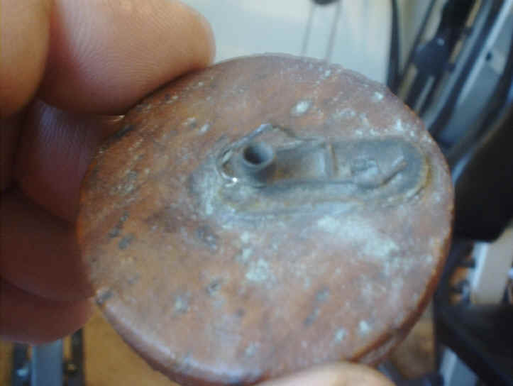
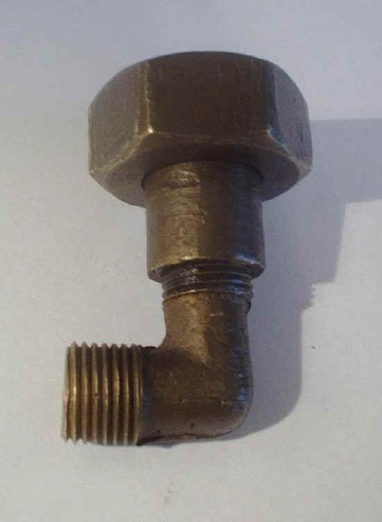
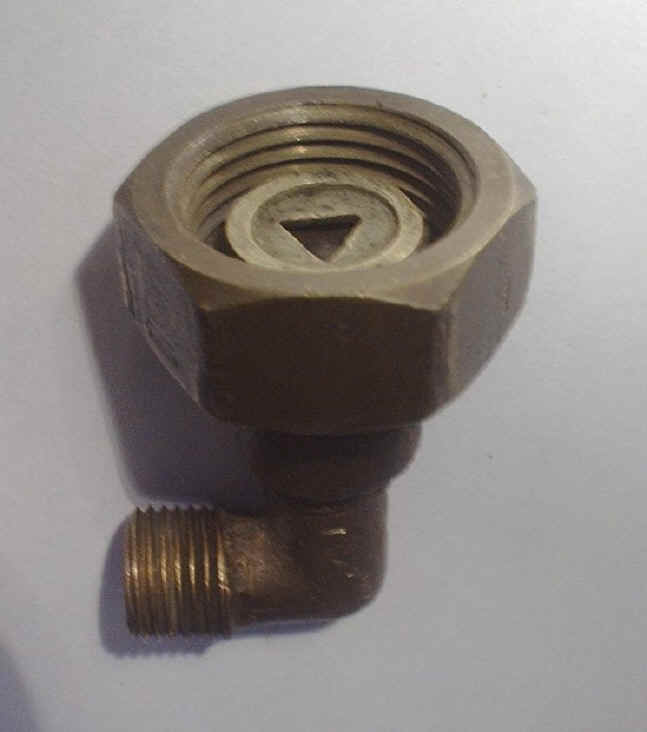
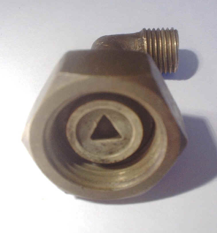
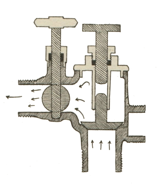
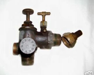
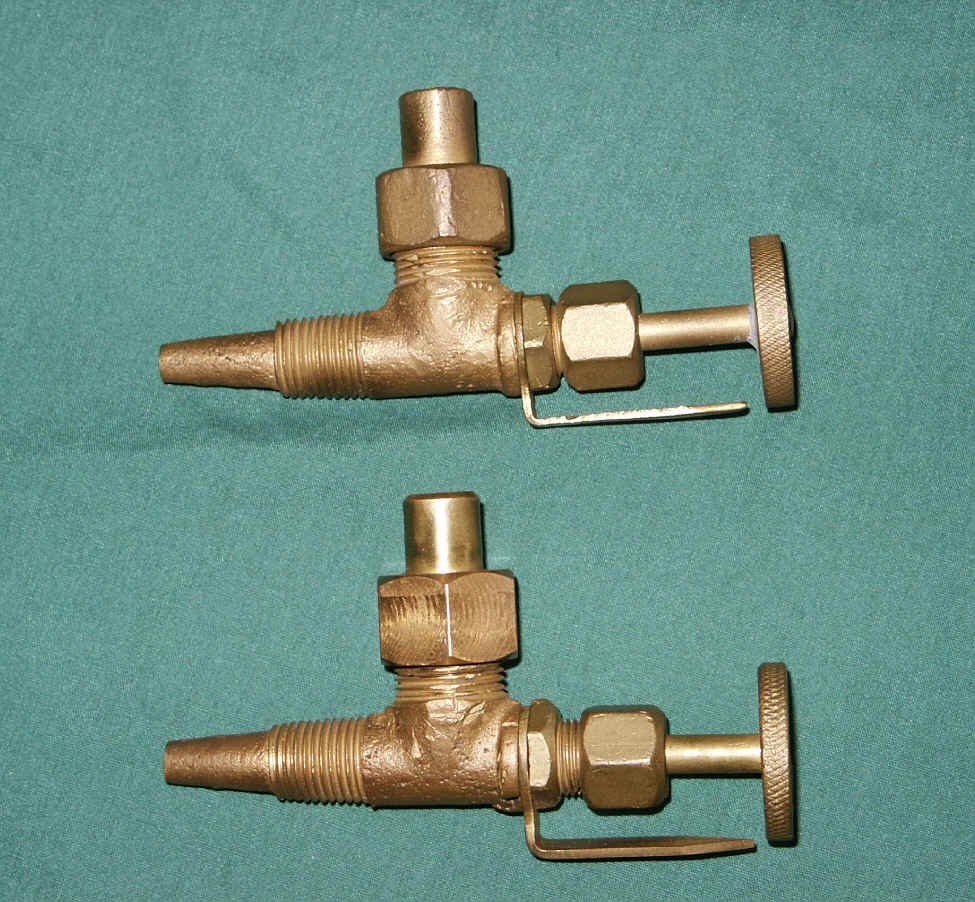
Detroit natural gas air intake valve.
______________________________________________________________________________________________________________
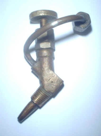
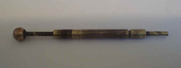
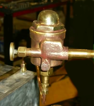
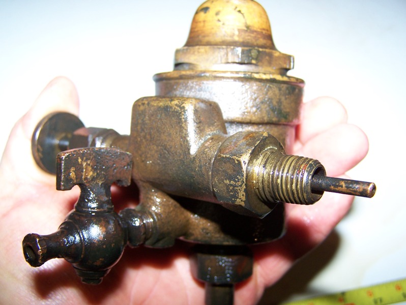
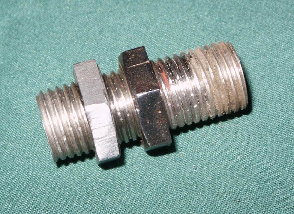
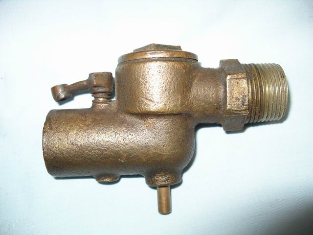
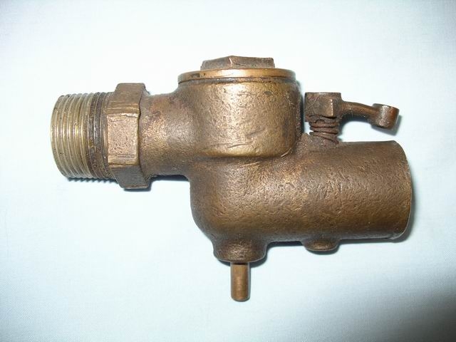
Some of the 3rd style fuel feeders had a primer cup valve that
was mounted to the top of the acorn cap or the side of the reservoir, This allowed you to prime the fuel reservoir after the engine had
set for a period of time and the fuel had evaporated or seeped down to the fuel tank. This
primer cup valve would
save you the trouble of having to find a wrench and remove the reservoir cap every
time. Injector tubes are made from standard 1/8" copper tubing with
1/16" inner
|
|
|
|
|
|
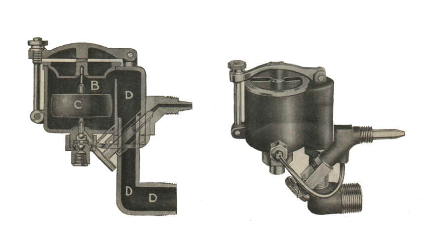
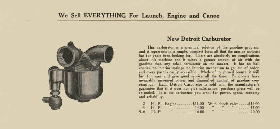
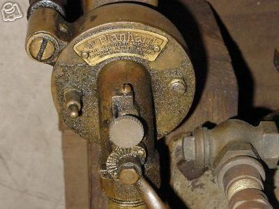
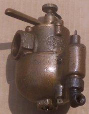
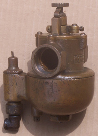
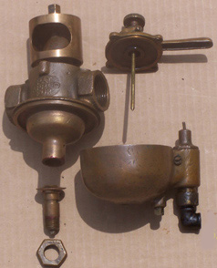
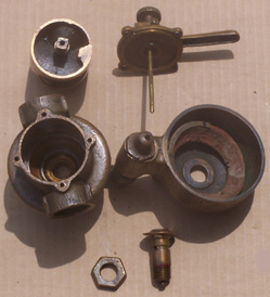
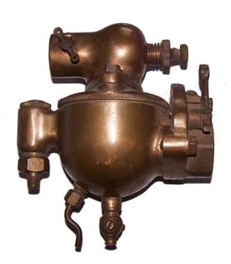
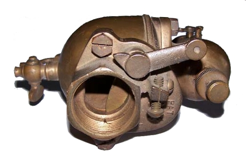
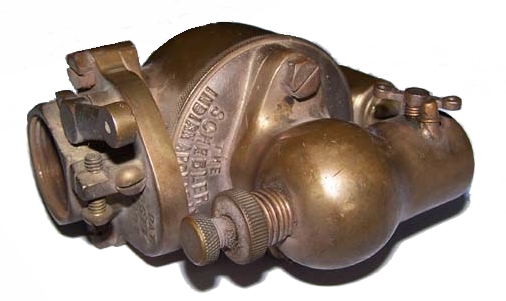
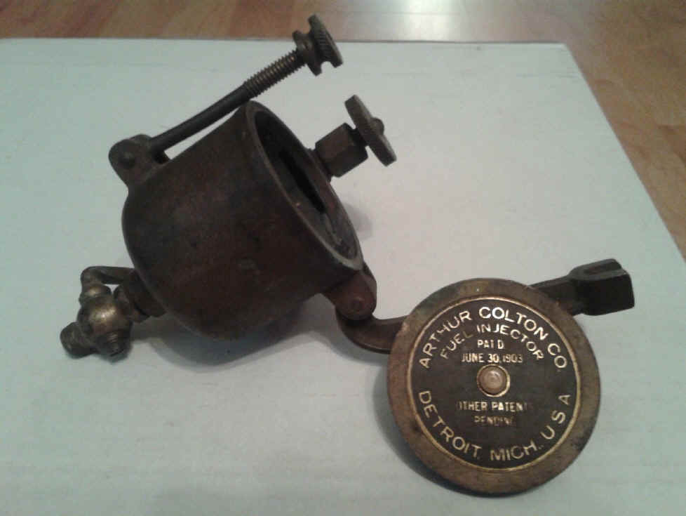
This carburetor was built by the PlanHard Manufacturing Co. Used on DEW, DMCSC, CEC
marine engines.
|
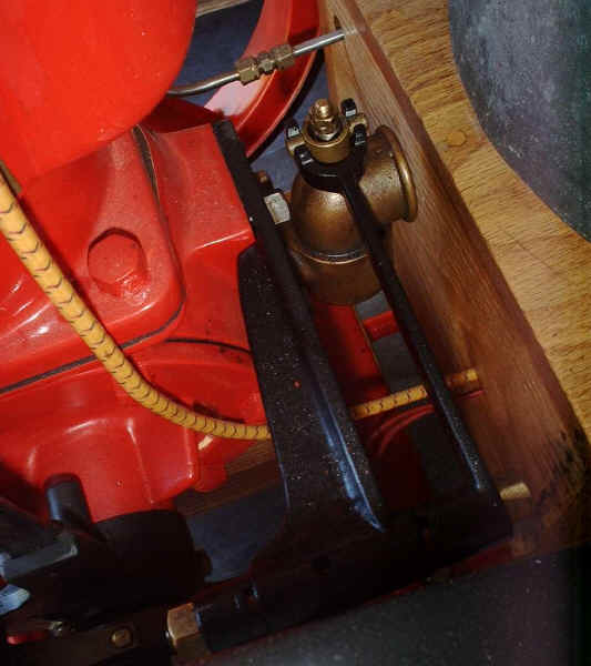
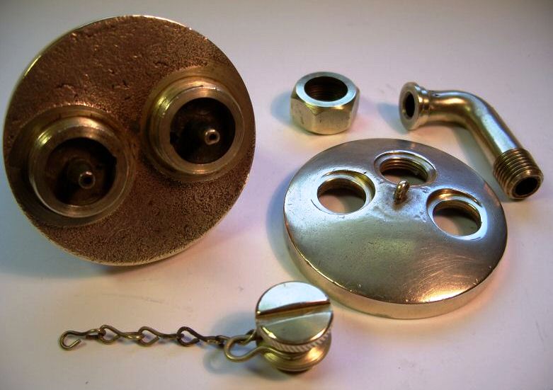
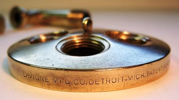
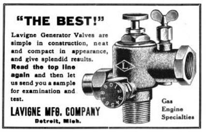 Lavigne Mfg. Co. also made a mixer that looks real close to the ones used on the Detroit engines. |
|
|
|
|
|
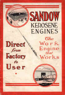
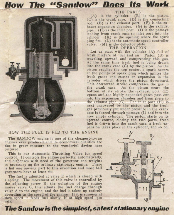
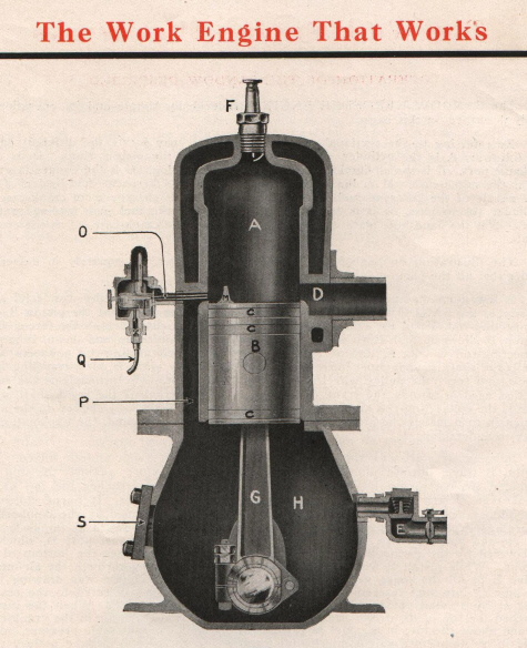
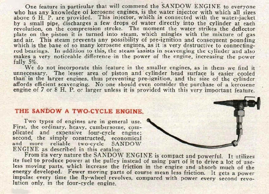
Water Injection |
|
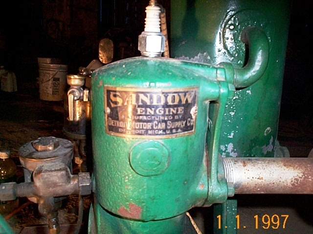
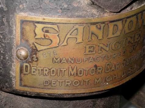
In the early 1900's most engine companies who manufactured kerosene type
engines used water injection. The literature below is from the Detroit Motor Car Supply Company catalog
about their Sandow engine
explaining why they use water injection. DEW, DMCSC, CEC all used water
injection on their larger
engines.
|
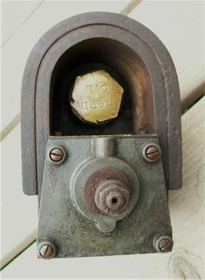
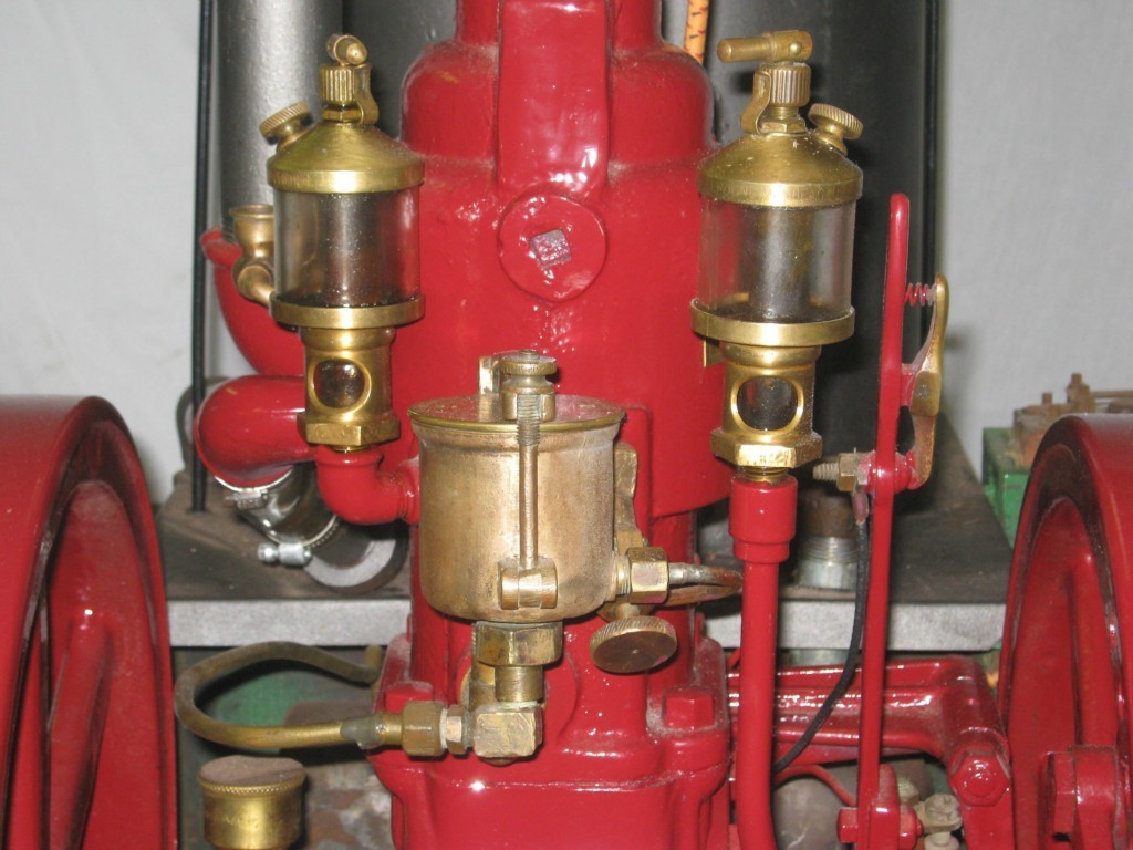
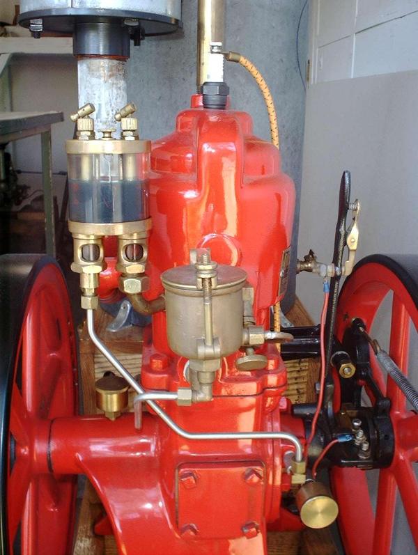
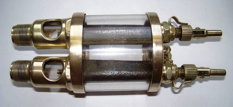
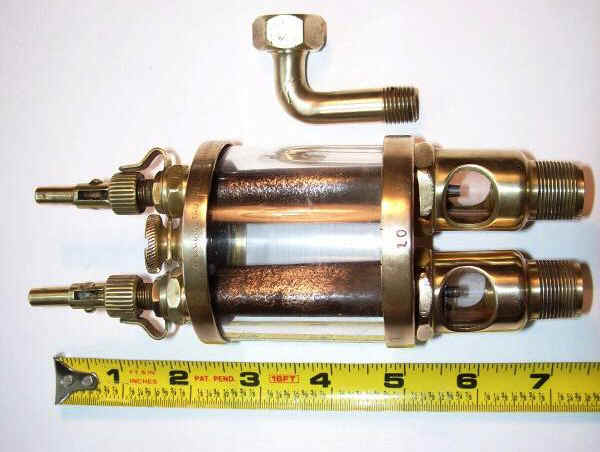
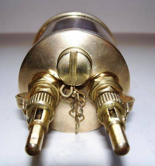
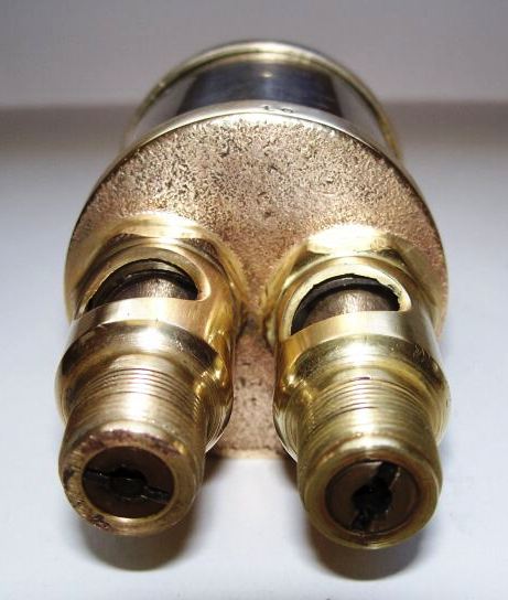
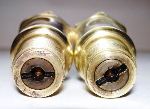
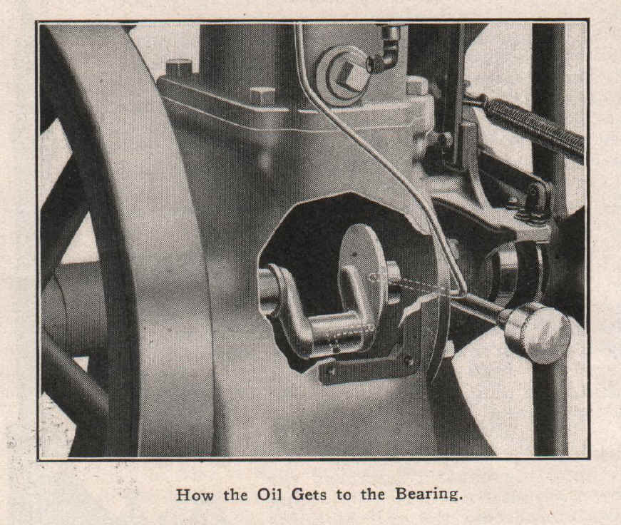
| Drip Feed Lubricator's |
|
Some time later a single lubricator
with two drip lines was introduced that did the same work of the two
single drip oilers but with only one oil reservoir. Some antique engine enthusiast
believe that the lubricators on the Detroit engines are sealed units and
oil is injected into the engine by pressure from the crankcase. I have
found no original literature or avertisements to support this theory. I
have original Detroit manuals, catalogs, Sales literature, advetisements
and none of them say anything about the Detroit having a pressure feed
oiling system and believe me if it did have this they would be using it
in their advertising to try and boost thier sales. The manuals states
that the lubrication system is drip feed and grease cups for the main
bearings. These types of oilers have a check ball below each drip sight
glass to keep air pressure and oil from blowing back into the oil
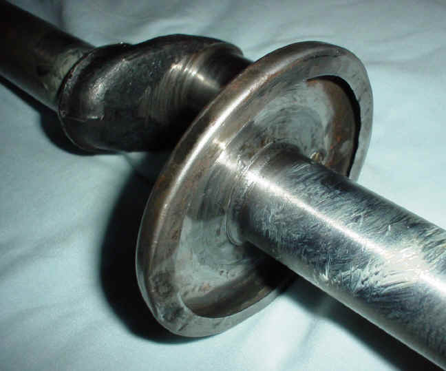
reservoir. Manuals do state that the lower connecting rod bearing is
positive feed lubrication but not from air pressure but from centrifical
force using a oil slinger ring mounted on the crankshaft. See photos
below.
|
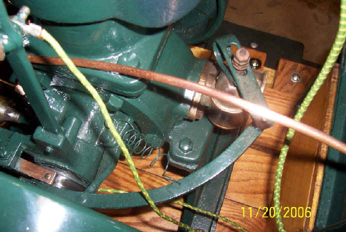
| DEW & Sandow Stationary Governor Linkages |
 Early Style Governor Linkage 1907-1912
|
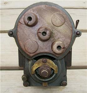
| Magneto's, Alternator's, Buzz coil's |
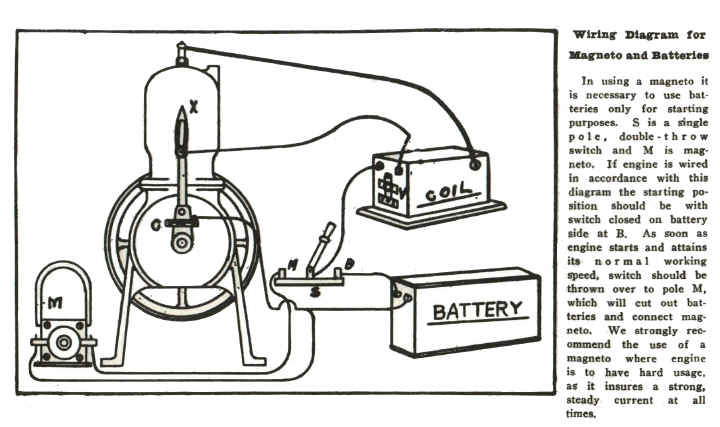 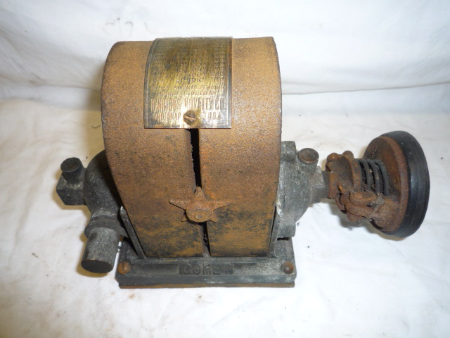
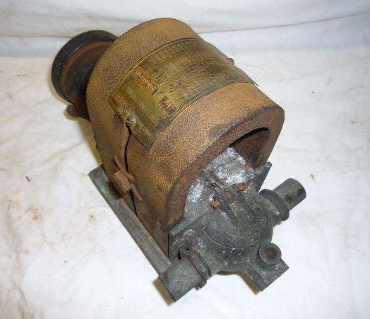
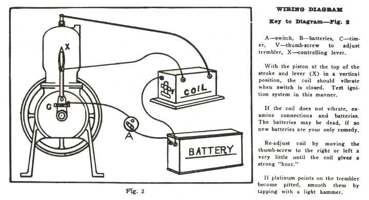
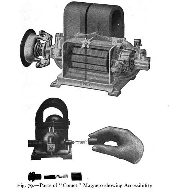 In the factory DEW parts catalog they call this a Comet Magneto sold for $9.00 new. This is actually a small alternator with a rubber friction wheel that you would drive against the flywheel, some times called a battery saver. You would start the engine using a dry cell battery and buzz coil. Once the engine was running good and steady you would flip a switch disconnecting the battery and connecting the alternator. Alternator would now supply alternating current (AC voltage) to the buzz coil. The buzz coil contact points last much longer using (AC) alternating current rather then (DC) direct current. For more information on ignition see DEW wiring diagram above. |
| Kingston Magneto |
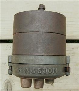
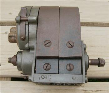
 Kingston magneto could be purchased as option for the big twin cylinder Detroit engines.
|
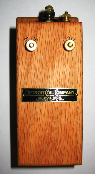
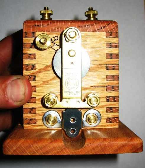
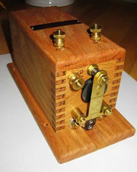
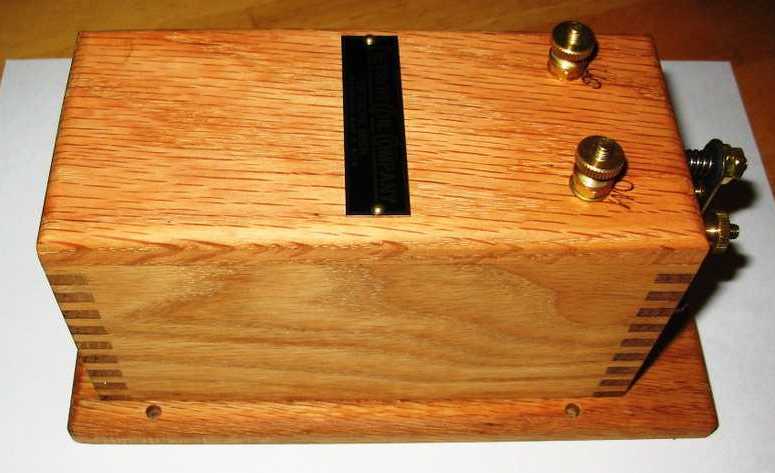
| Stationary Buzz Coil |
|
This is an identical reproduction of
the old Detroit buzz coils, even has the electronics potted in tar just like the
old original buzz coils. John Regan makes these Detroit style buzz coils & also reproduces the
model T ford style buzz coils. See website link for more
info. http://www.funprojects.com/
_________________________________________________________________________________________ |
|
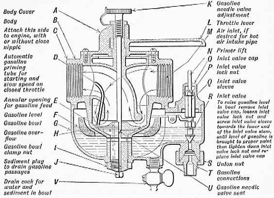
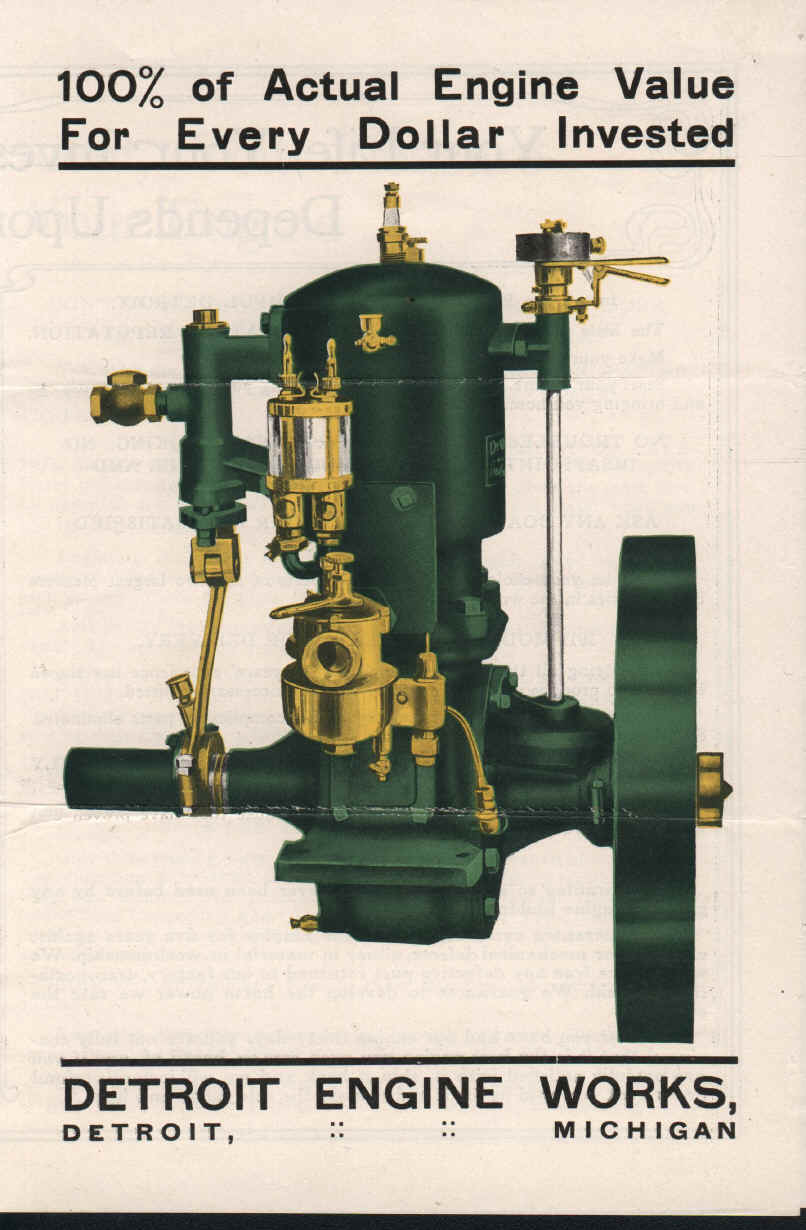
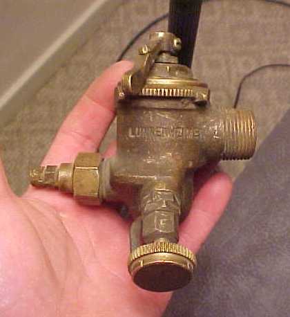
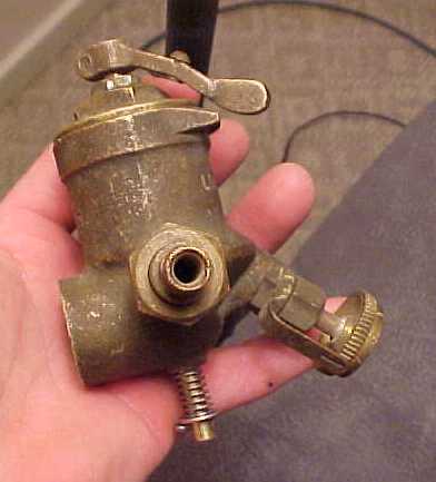
Marine & Stationary Engine Info |
|
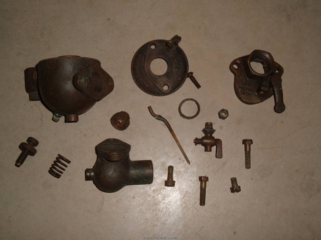
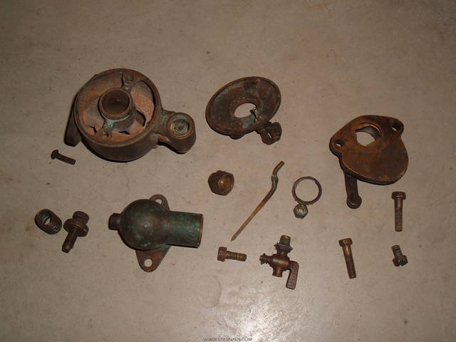
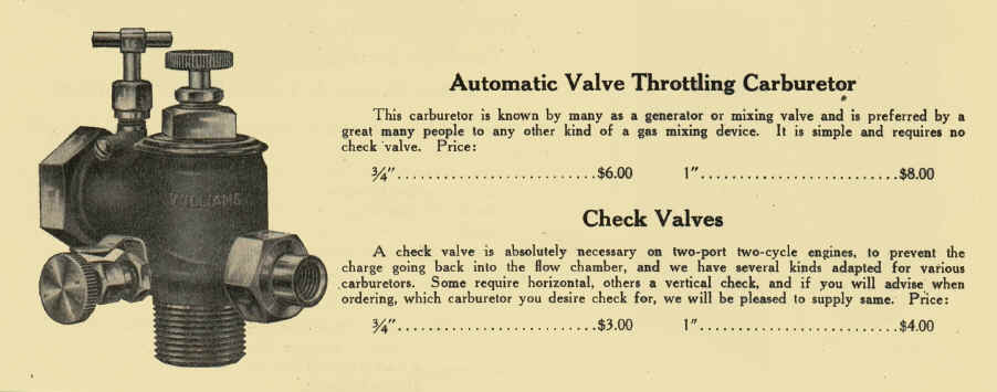
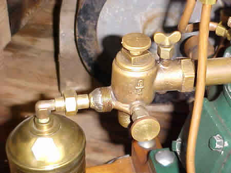
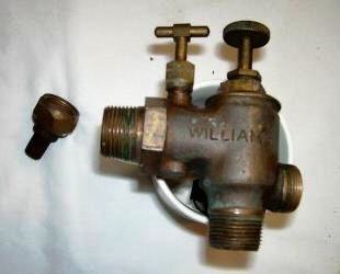
Research shows that DEW, DMCSC, CEC marine engines were
offered in many different configurations over the years. An assortment
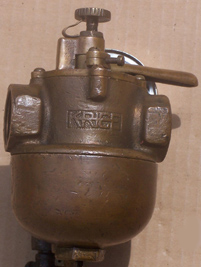
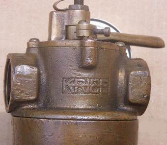
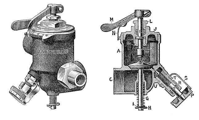
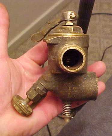
of carburetors and mixers manufactured by different companies, DEW,
Schebler, Lunkenheimer, Essex, Krice, Williams, Lavigne are just a few that are known
to have been used. Ben J. Middleditch manufactured the first
fuel injection systems that were used on some of these marine engines. Then DEW
manufactured three different styles of fuel feeder-injectors in the
proceeding years after.
* The 8hp was the only stationary engine
that had bolt on internal counter balance weights for the crankshaft.*
Source = (Parts
List Bulletin No. 111 Jan 1st 1912), (Parts
List Bulletin No. 300 March 1st 1916).
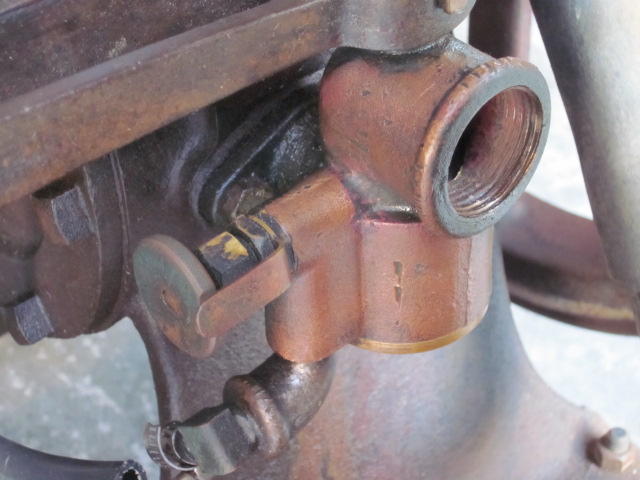
DEW & DMCSC (Stationary Engines with two flywheels) Some time between 1913 and 1914
a new cylinder style change was made on 5 hp all
the way up to 20 hp. Exhaust port changed from direct pipe thread into
the cylinder to bolt on flange type
manifold elbow. The bottom water inlet also changed to bolt on style
flange. The position of water port on top of cylinder changed by 90 degree's.
The place were the oil line screwed into the cylinder moved from the
left side of the cylinder to the right side. The (Lower Con Rod) oil
line that screwed into the crank case on the right was moved to the left
side. The 4hp and under engines still used the old style cylinders that
did not have the bolt on flange for the exhaust and lower water inlet. Single drip oiler's or double drip oiler's offered on all single
cylinder engines. These oilers came with check
valves built into them, This kept the crank case pressure from blowing
the oil in the line back into the oiler. One oil line
lubricated the big end of
the connecting rod. The second oil line lubricated the piston and the
small end of the connecting rod.
Some of the larger two cylinder
DEW engines did have pressure feed oil systems. A oil pump that was belted to the
crankshaft with multiple oil lines through out the engine. Sources
= (1909
DEW Catalog), (Parts
List Bulletin
No. III Jan 1st 1912), (Part List Bulletin No. III part 3 Nov 1st 1914), (1915 DEW Catalog).
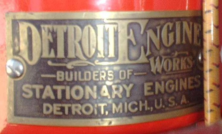
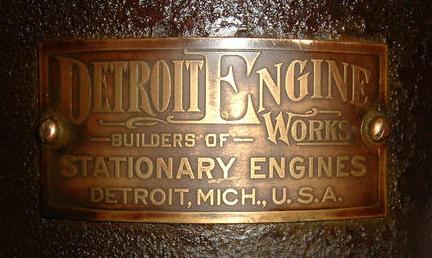
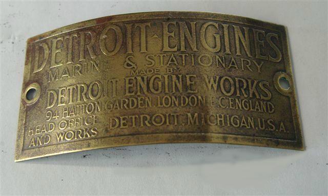
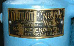
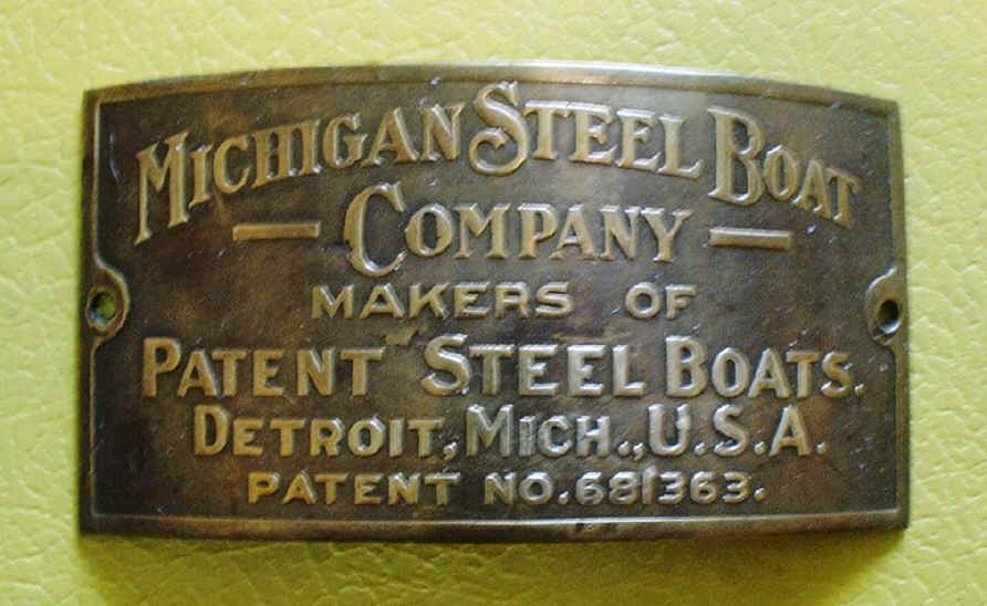
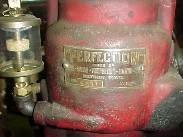
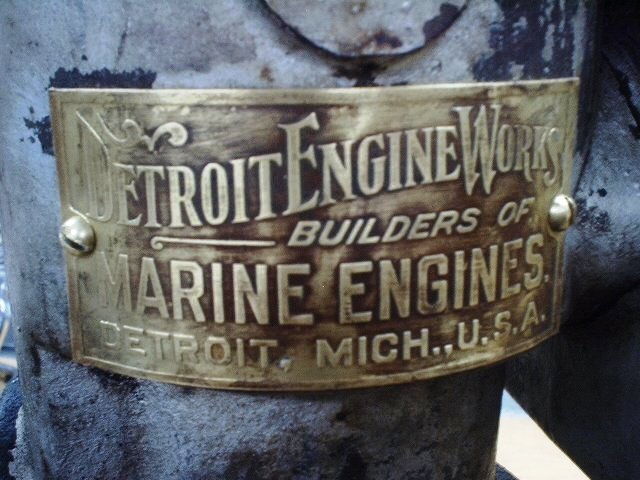
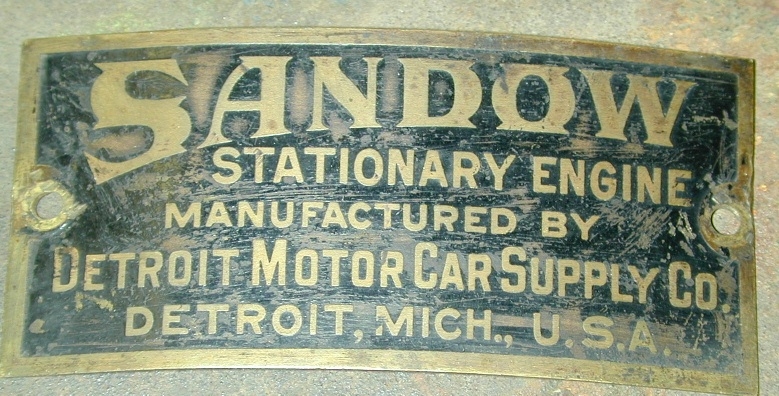
Below are some photo's of various engine tags that might be of interest to some of you collectors. |
| Main Menu |

